Full Wave Controlled Rectifier Circuit Diagram
Rectifier resistive menghitung kebutuhan Single phase half wave controlled rectifier with rl load Single phase half wave rectifier- circuit diagram,theory & applications
Full Wave Rectifier Circuit Diagram In Multisim - Grundlagen Http Sites
Phase single rectifier circuit current diodes controlled bridge half power rectification wave thyristor load flowing spite biased forward why supply Arduino 220v full wave controlled bridge rectifier Rectifier half phase controlled rl current
Rectifier arduino wave controlled circuit bridge 220v thyristor diagram simple project terminals connected grounded together
Full wave rectifier circuit diagram in multisimFull-wave rectifier circuit with resistive load. Rectifier multisim diode waveform tapped operation voltage circuitstoday circuitsRectifier transformer tapped waveform.
Rectifier circuit diagram .


Single Phase Half Wave Controlled Rectifier with RL Load - Electrical

Full Wave Rectifier Circuit Diagram In Multisim - Grundlagen Http Sites

Full-wave rectifier circuit with resistive load. | Download Scientific

Arduino 220V Full Wave Controlled Bridge Rectifier - Simple Circuit

Rectifier Circuit Diagram | Half Wave, Full Wave, Bridge - ETechnoG

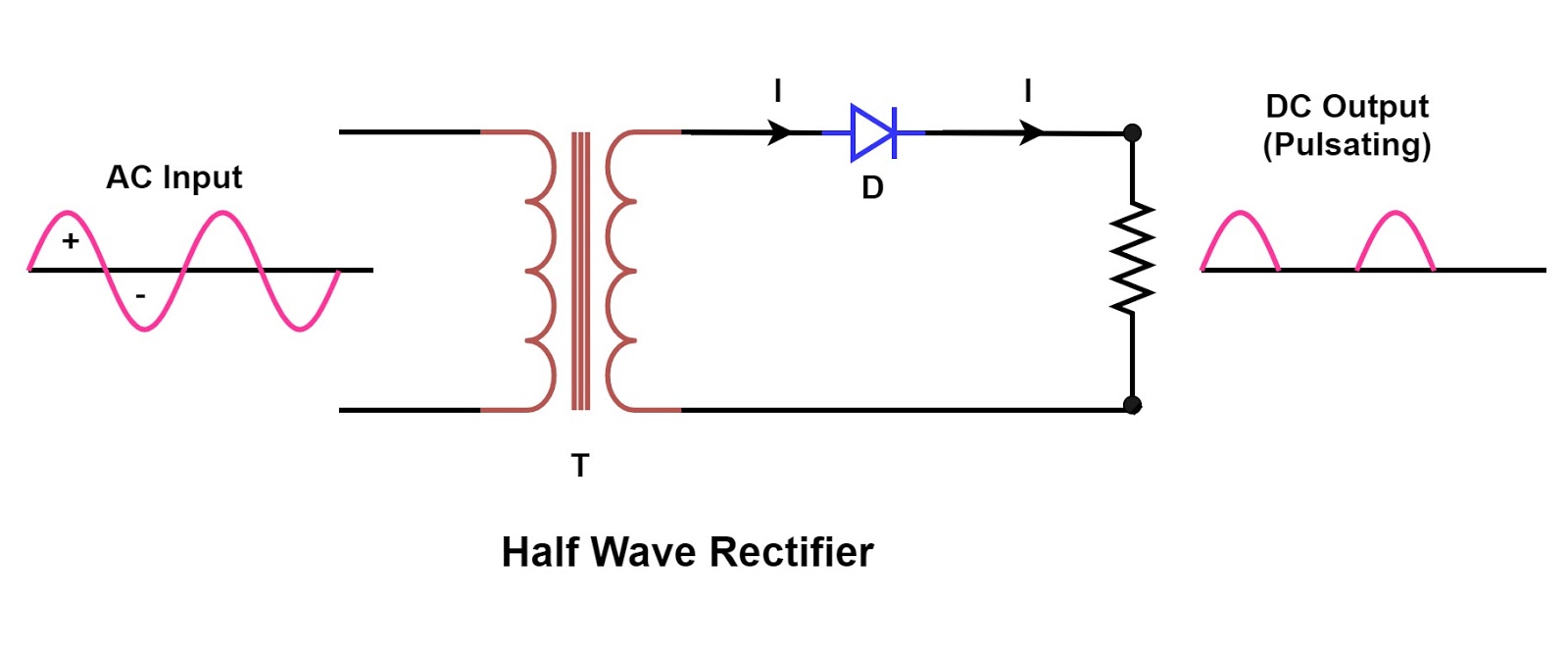
Single Phase Half Wave Rectifier- Circuit Diagram,Theory & Applications